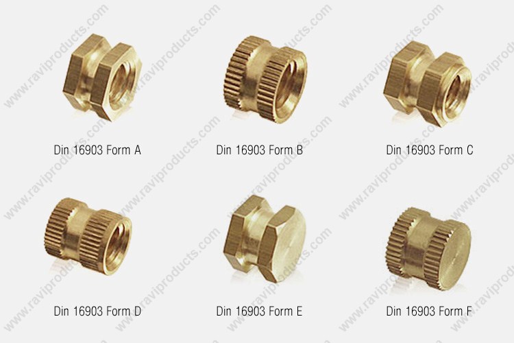
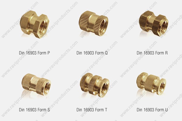
| Shape of sleeve | B, D | A, B, C, D | A, C | |||||||
Diameter d1 (6H) |
M 2 | M 2.5 | M 3 | M 3.5 | M 4 | M 5 | M 6 | M 8 | M 10 | M 12 |
a1 a2 b1 b2 |
0.8 0.9 0.8 0.8 |
0.9 1.0 0.8 0.8 |
0.9 1.2 1.2 1.0 |
1.0 1.6 1.4 1.0 |
1.2 1.8 1.4 1.0 |
1.6 2.0 1.8 1.0 |
1.8 2.5 2.4 1.0 |
2.0 4.0 4.0 1.0 |
3.0 4.0 4.0 1.0 |
3.5 5.0 5.0 1.0 |
b3 d2 H11 d3 h12 d4 |
0.8 1.6 3.2 2.7 |
1.0 2.05 3.4 3.0 |
1.2 2.5 3.8 3.4 |
1.4 2.9 4.5 4.0 |
1.4 3.3 5.0 4.5 |
2.5 4.2 6.4 5.5 |
3.0 5.0 7.4 6.8 |
4.0 6.8 10.4 8.8 |
6.0 8.5 13.0 11.0 |
7.0 10.3 17.0 13.0 |
d5 2) d6 h11 g l1 h12 |
3.5 3.5 0.1 2.3 |
3.8 3.8 0.1 2.6 |
4.2 4.2 0.1 3.0 |
5.0 5.0 0.1 3.5 |
5.5 5.5 0.1 4.0 |
7.0 7.0 0.1 5.0 |
8.0 8.0 0.16 6.0 |
- 10.0 0.16 8.0 |
- 12.5 0.2 10.0 |
- 16.0 0.2 12.0 |
l2 h12 r ≈ t ≈ s e ≈ |
3.5 0.3 0.5 - - |
4.0 0.3 0.5 - - |
4.5 0.3 0.5 5.0 5.8 |
5.5 0.3 0.5 5.5 6.35 |
6.0 0.4 0.5 6.0 6.9 |
7.5 0.6 0.6 7.0 8.1 |
9.0 0.6 0.6 9.0 10.4 |
12.0 0.6 - 11.0 12.7 |
15.0 0.6 - 14.0 16.2 |
18.0 0.6 - 19.0 21.9 |
| Shape of sleeve | F, H | E, F, G, H | E, G | |||||||
Diameter d1 (6H) |
M 2 | M 2.5 | M 3 | M 3.5 | M 4 | M 5 | M 6 | M 8 | M 10 | M 12 |
a1 a2 b1 b2 |
1.0 1.0 1.2 0.8 |
1.0 |
1.2 |
1.4 |
1.4 |
1.5 |
1.8 |
2.5 |
3.0 |
3.5 |
b3 f +0.2 d2 H12 d3 h12 |
1.5 |
1.6 |
1.8 |
2.2 |
2.5 |
3.0 |
3.5 |
4.5 |
6.0 |
7.0 |
d4 d5 2) h11 d6 h11 d7 |
2.7 |
3.0 |
3.4 |
4.0 |
4.5 |
5.5 |
6.8 |
8.8 |
11.0 |
13.0 |
g l1 3) h14 l2 3) h14 l3 h12 |
0.1 |
0.1 |
0.1 |
0.1 |
0.1 |
0.1 |
0.16 |
0.16 |
0.2 |
0.2 |
| l4 h12 r t s e |
4.3 |
4.8 |
5.3 |
6.5 |
7.0 |
8.5 |
10.0 |
13.5 |
16.5 |
19.5 |
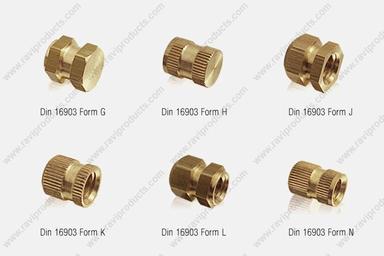
| Shape of sleeve | K, N | J, K, L, N | J, L | |||||||
Diameter d1 (6H) |
M 2 | M 2.5 | M 3 | M 3.5 | M 4 | M 5 | M 6 | M 8 | M 10 | M 12 |
a1 a2 b1 b2 |
1.0 |
1.2 |
1.4 |
1.5 |
1.5 |
1.8 |
2.0 |
2.8 |
3.5 |
4.0 |
b3 d2 H12 d3 h12 d4 |
1.2 |
1.2 |
1.2 |
1.5 |
1.8 |
2.0 |
2.5 |
3.0 |
3.5 |
4.0 |
d5 2) ≈ d6 h11 d7 f +0.2 |
3.5 |
3.8 |
4.2 |
5.0 |
5.5 |
7.0 |
8.0 |
- |
- |
- |
l1 h14 l2 h14 l3 h12 l4 h12 |
2.3 |
2.6 |
3.0 |
3.5 |
4.0 |
5.0 |
6.0 |
8.0 |
10.0 |
12.0 |
| s e ≈ g r ≈ t ≈ |
- |
- |
- |
- |
6.0 |
7.0 |
9.0 |
11.0 |
14.0 |
19.0 |
| Shape of sleeve | Q, S | P, Q, R, S | P, R | |||||||
Diameter d1 (6H) |
M 2 | M 2.5 | M 3 | M 3.5 | M 4 | M 5 | M 6 | M 8 | M 10 | M 12 |
a1 |
1.0 |
1.2 |
1.4 |
1.5 |
1.5 |
1.8 |
2.0 |
2.8 |
3.5 |
4.0 |
b3 |
1.6 |
1.6 |
1.8 |
2.0 |
2.8 |
3.5 |
4.0 |
5.5 |
6.0 |
7.0 |
d5 2) |
3.5 |
3.8 |
4.2 |
5.0 |
5.5 |
7.0 |
8.0 |
- |
- |
- |
g |
0.1 |
0.1 |
0.1 |
0.1 |
0.1 |
0.1 |
0.16 |
0.16 |
0.2 |
0.2 |
l4 h12 |
5.3 |
6.0 |
7.0 |
8.0 |
7.0 |
10.8 |
12.8 |
16.6 |
20.0 |
23.8 |
| Shape of sleeve | T | T, U | U | ||||||||
Diameter d1 (6H) |
M 2 | M 2.5 | M 3 | M 3.5 | M 4 | M 5 | M 6 | M 8 | M 10 | M 12 | M 16 |
a1 |
0.6 |
0.6 |
0.8 |
0.8 |
0.8 |
1.0 |
1.2 |
- |
- |
- |
- |
b1 |
1.2 |
1.4 |
1.5 |
1.7 |
1.9 |
2.2 |
2.7 |
- |
- |
- |
- |
d2 H11 |
1.6 |
2.05 |
2.5 |
2.9 |
3.3 |
4.2 |
5.0 |
6.8 |
8.5 |
10.3 |
14.1 |
d6 h11 |
4.5 |
5.0 |
5.5 |
6.0 |
7.0 |
9.0 |
10.0 |
12.0 |
15.0 |
18.0 |
24.0 |
l2 h14 |
- |
- |
- |
- |
8.0 |
10.0 |
12.0 |
16.0 |
20.0 |
24.0 |
32.0 |
t ≈ r ≈ |
0.5 |
0.5 |
0.5 |
0.5 |
0.5 |
0.6 |
0.6 |
0.6 |
0.6 |
0.8 |
0.8 |